- Submissions

Full Text
Evolutions in Mechanical Engineering
A Comparison Between Two Methods of Sheet Hydroforming By Simulation
Forouhandeh F*
Department of Engineering, Shahrood Branch, Iran
*Corresponding author:Forouhandeh F, Department of Engineering, Shahrood Branch, Iran
Submission: November 5, 2018;Published: December 17, 2018

ISSN 2640-9690 Volume1 Issue2
Abstract
Sheet hydroforming is a recent common process for sheet metal forming due to several advantages like better surface quality of products, more drawing ratio, less needing to secondary operation etc. Forming of Titanium alloys are very suitable /applicable because of ability to tolerate work in elevated temperature. In this paper, two different methods have been compared using finite element method and advantages of more suitable one has been illustrated.
Keywords: Sheet hydroforming; CAE; Finite element simulation; CP titanium
Introduction
Metal forming of light alloys has become very popular due to high strength to weight ratio product formation by various forming processes. Automobile, Sanitary, aerospace etc. are some of the common sectors due to the capability of light alloys being formed in a variety of shapes by variety of forming methods/ operations. Hydroforming is a popular forming process today to meet the challenges of various industries. Tube hydroforming [THF] and sheet hydroforming [SHF] are relatively complex manufacturing processes. It has been explained that SHF process is better than the conventional manufacturing done via stamping and welding such as: (i) Part consolidation resulting in weight reduction of the component, (ii) weight reduction through more efficient section design and tailoring of the wall thickness, (iii) reduced tooling cost, (iv) improved structural strength and stiffness, (v) less number of secondary operations, (vi) reduced dimensional variation, (vii) significant reduction in spring back effects and (viii) reduced scrap rate [1]. The analysis and performance of the process depends on many factors such as part geometry and design, material and process parameters and the boundary condition of forming.
The best and easiest way to study the behavior of such alloys is by Finite Element Method and Computer Aided Engineering Based Procedure. The technology of product manufacturing by THF and SHF is developing very fast to shape complex profiles of sheet products. Titanium due to some special properties like high strength to weight ratio and ability to work in high temperature condition has become unique and applicable in aerospace industries. Although sheet metal forming of Titanium is very difficult due to high spring back, strength against deformation in room temperature and low ductility but in case of appropriate deformation, products are very strong and applicable for light structures.
In this paper a finite element simulation DEFORM 3D package has been used with appropriate conditions to achieve defect free product with minimum forming load has been introduced. Two different methods of sheet hydroforming; first with die cavity without punch and second with punch and without die cavity has been compared. Recent over view on hydroforming especially sheet hydroforming has been presented by author [1]. There are some challenges such as optimization of forming process parameters related to SHF of CP Titanium and Titanium alloys and its experimental study. Microstructure analysis of hydroformed parts is another area which is still to be exploded in the field of sheet hydroforming process. Better surface quality reduced dimensional variation and smooth strain are some of the benefits of SHF in comparison to conventional method like deep drawing.
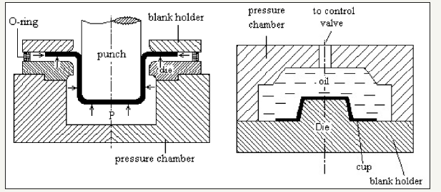
In sheet hydroforming process (Figure 1a), after blank setting and blank holding, a punch pushes the sheet metal into the die cavity, while oil/liquids back pressure is applied on other side by a press to flow the sheet metal tightly into the punch to generate a shape. At the same time the liquid in the die cavity will flow out between the upper surface of the die and the sheet metal. Therefore, fluid lubrication reduces the frictional force [2]. Sheet hydroforming is classified into two types: sheet hydroforming with punch (SHF-P) and sheet hydroforming with die (SHF-D). In SHF-P (Figure 1a) the hydraulic fluid is replaced with the die, while in SHF-D (Figure 1b) the hydraulic fluid is replaced with the punch. Absence of either punch or die in SHF process reduces the tooling cost.
Figure 1:Schematic diagram of sheet hydroforming: (a) sheet hydroforming-punch, (b) sheet hydroforming-die.
Computer Aided Engineering (CAE) Simulation for SHF Process
CAE is a process wherein many tools (models & simulation) are used to study a process or behavior of a system. In this work CAE process has been used to model and simulate using Deform 3D package. Different parameters like friction coefficient, blank holding force, ram speed, working temperature and die and punch corner radii have been changed. Appropriate condition has been selected to achieve minimum total forming load and defects.
Since, Cup hydroforming process is affected by thinning and stretching due to high hydraulic pressure different simulations are carried out to minimize the load requirement and to minimize the thinning. Simulation results under different types of boundary conditions are used to choose the best way out of the iterative numerical experiments. To conduct a SHF simulation using computer, first it needs to represent the metal forming system to be simulated in its detailed geometry content, i.e., to create the computer models of the deformation system and the metal forming process. Blank holding has been applied as a selected area between two concentric circles outside the die cavity and inside the sheet. Material data and some initial parameters for cup hydroforming simulation have been presented in Table 1.
Table 1:Material data and some initial parameters for cup hydroforming simulation.
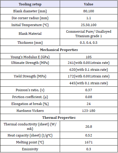
Details of symmetric die (100×100×50mm) and die cavity: half sphere, radius: 25mm. Initial boundary conditions: Applied fluid pressure and blank holding pressure are up to 5Mpa and 2MPa respectively. Friction value for Titanium sheet is taken as 0.08 (coulomb/sliding friction) [3]. Material type is selected as Elastoplastic (in sheet metal forming) as recommended in of DEFORM 3D User’s Manual [4,5].
Generally, simulation work can be performed in two different conditions. First, simple sheet hydroforming without using proper shaped punch and with exact die cavity (Figure 1b) and second, hydro mechanical cup/deep drawing with using exact shaped punch and with container without exact die cavity (Figure 1a). In the first condition, there is fluid (nodal) between a simple cylindrical shape punch and sheet; punch with pushing fluid above the sheet. In second condition, punch move down from upside and there is backward fluid pressure in the container. Therefore, fluid pushes the sheet towards punch. Hence there is no die cavity in this condition, friction will be very low and therefore forming load will be less in comparison to first condition. Also precision of punch geometry (especially any angle) is so considerable. It has been observed that setting the working temperature at 100 oC, 5MPa fluid pressure and blank holding pressure 2MPa (as initial boundary conditions) give appropriate results [6].
Hydro Mechanical Cup Drawing and Design Modification
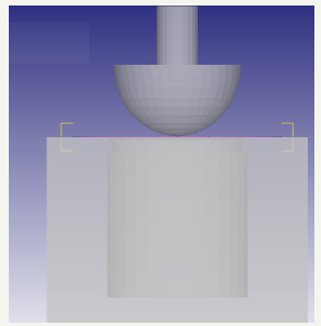
The actual punch is shown in Figure 2 along with the movement in downward direction. Another major change is done by designing a die container instead of die cavity. This method is called hydro mechanical cup drawing having backward fluid pressure from down side. This modification results in fewer loads as compared to the initial design. Table 2 shows comparison between the two conditions. Cup hydroforming process is affected by thinning and stretching due to high hydraulic pressure. Different simulations are carried out to minimize the load requirement and to minimize the thinning. Simulation results shows the deformation behavior for different types of boundary conditions and results so obtained are used to choose the best way out of it for actual experiments.
Table 2:Comparison between first condition (without container) and second condition (with container) for requirement forming load.

Figure 2:Cup forming with punch and fluid container.
Finite element preprocessing
To conduct a SHF simulation using computer, first it needs to represent the metal forming system to be simulated in its detailed geometry content, i.e., to create the computer models of the deformation system and the metal forming process. Blank holding has been applied as a selected area between two concentric circles outside the die cavity and inside the sheet. The solid models of die and sheet (blank), are built. Details of symmetric die are 100×100×50mm and die cavity: half sphere, radius: 25mm.
Initial boundary conditions
Applied fluid pressure and blank holding pressure are up to 5Mpa and 2MPa respectively. Friction value is taken as 0.08 (coulomb/sliding friction) because material type is selected Elastoplastic (in sheet metal forming) and this is recommendation of DEFORM as well. Material properties of CP Titanium grade 1 and some initial parameters have been given in Table 3 & Figure 3.
Figure 3:Effective stress distribution for symmetric shape.
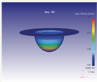
Maximum stress due to effect of forming process is high. Also strain rate is high and stress in Titanium depends on strain rate as well. After design modification, Stress will be decreased. In the other shapes stress will be decreased. When the strain rate rises more than 0.1(1/s), (for example 0.2 or more) ultimate point and effective stress jump very high. In fact, these are results of FEM and in preprocessing every value has been entered according to the literatures. Therefore, effective stress did not exceed the ultimate point.
Result and Discussion
It is observed that minimum load 4.74 ×10⁴ Newton is required when blank holding pressure (BHP) of 2MPa is applied. There is further decrease in load requirement when the BHP increases but as discussed earlier it causes non-uniform thickness distribution. Thus, appropriate loading cycle can be directly plotted by the use of post processor. All these results are for simple sheet hydroforming without punch and with liquid pressure from upper side of die surface.
Conclusion
In this work, sheet hydroforming simulation has been performed. Two different methods of sheet hydroforming processes have simulated and compared. Based on result more appropriate method has been introduced.
References
- Forouhandeh F, Kumar S, Ojha SN (2013) Recent development in micro hydroforming. Advances in Mech Eng 5: 1-14.
- Hosseinzadeh M, Mostajeran H, Bakhshi-Jooybari M, Gorji A, Norouzi S, et al. (2009) Novel combined standard hydromechanical sheet hydroforming process. I MechE J Eng Manuf 224(3): 447-457.
- Kumar S (2006) Report on DST Research project [III.S (109)/2001-SERC (ENGG)] on ‘Knowledge based automatic system for near-net shape manufactured products using extrusion. pp. 301-305.
- Forouhandeh F (2013) Development of a sheet hydroforming process for metals and alloys, PhD thesis, Department of Mechanical Engineering, Indian Institute of Technology (Banaras Hindu University), India.
- DEFORM-3D User’s Manual, Version 10, Scientific Forming Technologies Corporation.
- Lange K (1996) Hand book of metal forming, SME, pp.40-43.
© 2018 Forouhandeh F. This is an open access article distributed under the terms of the Creative Commons Attribution License , which permits unrestricted use, distribution, and build upon your work non-commercially.
 a Creative Commons Attribution 4.0 International License. Based on a work at www.crimsonpublishers.com.
Best viewed in


.jpg)


 Editorial Board Registrations
 Submit your Article
 Refer a Friend
 Advertise With Us
.jpg)


.jpg)


.bmp)
.jpg)
.png)
.jpg)


.jpg)


.png)

.png)


.png)


